After working mostly with application level software and web development, I wanted to try something new. That search led me to chip8, after I found it can be built in one or two days.
What is Chip8?
Wikipedia documents Chip8 as an interpreted programming language, which was mostly run on 8-bit computers.
So what would we need to build a chip8 interpreter?
First, we will need a reference on how the chip8 interpreted language works and the related semantics. Then we will need a test program to check if our implementation is correct. And at the final stage, we should be able to do something cool, like play a game or two in our interpreter 😁
After a bit of searching I found the documentation from CowGod, Which actually is the only document you need. For the test rom, I found this link which has a collection of ROMs including test ROMS, demos and games. Since now I have everything I needed, it is time to get started.1
What is our tech stack?
Before we begin, let’s decide on the technology stack.
- We will use devenv along with direnv for setting up the development environment. This lets us have a declarative way of setting up the development environment with all the required dependencies.
- For PL, we will Golang along with SDL2 bindings for handling inputs and rendering.
- For IDE, I use GoLand
Now that we have a plan, let’s get started.
Setting up the stage
First we need to set up the developer environment along with a simple Golang Hello World program to confirm everything is working fine. Please refer commit for this step.
Now running devenv shell and running go run src/main.go should print “Hello Chip8” to our console.
Drawing something on the screen
Now let’s try to draw something on the screen using the SDL2 bindings. For this we need to add the required C/C++ libraries for SDL2 bindings to work. You can find all the details here. Luckily for us, it is pretty easy with devenv, as can be seen here.
Now let’s draw a rectangle on the screen based on the example from README of SDL2.
package main
import "github.com/veandco/go-sdl2/sdl"
func main() {
if err := sdl.Init(sdl.INIT_EVERYTHING); err != nil {
panic(err)
}
defer sdl.Quit()
window, err := sdl.CreateWindow("test", sdl.WINDOWPOS_UNDEFINED, sdl.WINDOWPOS_UNDEFINED, 800, 600, sdl.WINDOW_SHOWN)
if err != nil {
panic(err)
}
defer window.Destroy()
surface, err := window.GetSurface()
if err != nil {
panic(err)
}
surface.FillRect(nil, 0)
running := true
for running {
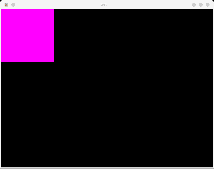
rect := sdl.Rect{0, 0, 200, 200}
colour := sdl.Color{R: 255, G: 0, B: 255, A: 255} // purple
pixel := sdl.MapRGBA(surface.Format, colour.R, colour.G, colour.B, colour.A)
surface.FillRect(&rect, pixel)
window.UpdateSurface()
for event := sdl.PollEvent(); event != nil; event = sdl.PollEvent() {
switch event.(type) {
case *sdl.QuitEvent:
println("Quit")
running = false
break
}
}
sdl.Delay(330)
}
}Doing a go mod tidy along with go run src/main.go we should see a purple rectangle on the screen as can be seen below.
You can see the corresponding commit here.
Now that we can draw on screen, let’s now go to the meat of the project.
Building BareBones Interpreter
As can be seen in the cowgod page, we will need the below parts for an Interpreter/Emulator.
- A CPU along with Registers and Timer to run the instructions.
- Memory to store the state / instructions / data
- A display to draw
- Keyboard to take input from the user
- Sound, which we will skip
To accommodate more functionality, let’s refactor our code a bit. So let’s introduce a core folder with separate files for the constituent parts. Also introduce an Emulator to tie all the parts together.
So our Emulator can look like below. Please note that the structs below will evolve as we proceed further.
type Emulator struct {
cpu      Cpu
mem      Memory
display  IDisplay
sound    Sound
input    Input
window   *sdl.Window
renderer *sdl.Renderer
texture  *sdl.Texture
running  bool
}
The CHIP8 is an 8-bit CPU. We can represent the CPU as below.
type Cpu struct {
	internals CpuInternals
	display   IDisplay // We put it here so that CPU can easily update the display. This is a Q&D way of doing it.
	sound ISound
}

type CpuInternals struct {
	V     [16]byte // 8bit general purpose registers
	I     [2]byte // 16bit register to store memory addresses
	Delay byte // Delay register which is decremented at 60Hz. This is used for timing operations
	Sound byte
	PC    uint16 // Program Counter register 16-bit
	SP    uint8 // Stack pointer 8bit, pointing to top of stack
	Stack [16]uint16 // 16-bit stack
}
The Memory in CHIP8 is 4KB. RAM starts at 0x000 and memory address from 0x000 to 0x1FF is reserved for interpreter. 0x200 is the memory where programs starts.
type Memory struct {
	Mem          [4096]byte
}
The Display is a 64x32 pixel monochrome display. Further along we will need more knowledge about the display like how the sprites are displayed and so on, which we will discuss as required.
type Display struct {
	screen [64][32]byte
}
Since the code changes are long, but trivial, I will refer you to the commit
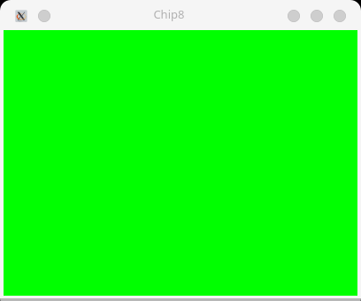
Now when we do go run cmd/main.go, we should see a green screen as below, which shows our refactoring was successful, and we can indeed see the content of the Display.screen from Emulator on our real computer :)
Now that we have our display working, let’s add functionality to load a ROM to memory. Once we have the instructions in memory, then we can start building our CPU, which can interpret those instructions.
Loading ROMs to memory
As you can already guess, this step is trivial. We simply need to read the binary file with os.ReadFile and store it in the Memory struct. The file we use is BC_test.ch8 from BestCoder)
The gist of functionality is shown below.
type Memory struct {
    Mem          [4096]byte
}

func (m *Memory) LoadDisk(data []byte) {
	for i := 0; i < len(data); i++ {
		m.Mem[loadAddress+i] = data[i]
	}
}

rom, _ := os.ReadFile("./roms/BC_test.ch8")
m.LoadDisk(rom)
You can find the full code in this commit.
Now let’s proceed to the most exciting part, building our CPU.
Building the Instruction Interpreter (CPU)
Chip-8 language has 36 instructions. All instructions are fixed size (2 bytes), where most significant byte is first. The convention used in above link is as follows.
nnnor addr - a 12 bit value, lowest 12 bits of instructionnor nibble - a 4 bit value, lowest 4 bits of instructionx- a 4 bit value, lower 4 bits of high byte of instructiony- a 4 bit value, upper 4 bits of low byte of instructionkkor byte - 8-bit value, lowest 4 bits of instruction
Let’s take a look at one instruction, 7xkk, which stands for ADD Vx, byte. It adds the value kk to register Vx.
Similarly 8xy0, which stands for LD Vx, Vy, which stands for Vx = Vy
You can find all instructions with details here There are instructions related to control flow, keyboard events, timers and drawing to screen. Let’s take a look at how most control-flow related instructions are implemented.
func (cpu *Cpu) executeInstruction(inst []byte) {
	state := &cpu.internals
	high, x, y, low := utils.GetNibbles(inst)
	hexString := hex.EncodeToString(inst)
	switch {
	case hexString == "00e0":
		// 00E0 Clear Screen
		cpu.display.clearScreen()
		state.PC += 2
	case hexString == "00ee":
		// 00EE, Return, sets Program Counter to top of stack and substracts 1 from Stack Pointer
		state.PC = state.Stack[cpu.internals.SP-1]
		state.SP -= 1
	case high == 1:
		// 1nnn, Jump to addr, set Program Counter to addr
		state.PC = binary.BigEndian.Uint16([]byte{x, inst[1]})
	case high == 2:
		// 2nnn, Call subroutine at addr, push Program Counter to stack
		state.Stack[state.SP] = state.PC
		state.SP += 1
		state.PC = binary.BigEndian.Uint16([]byte{x, inst[1]})
		......
The GetNibbles(inst) is as follows.
// GetNibbles This takes byte of length 2
// Returns a,b,c,d when abcd is provided where a,b,c,d are 4-bits in length
func GetNibbles(inst []byte) (byte, byte, byte, byte) {
	if len(inst) != 2 {
		panic("Pass 2 byte instructions only")
	}
	b1 := inst[0]
	b2 := inst[1]

	a := (b1 & 0b11110000) >> 4
	b := b1 & 0b00001111
	c := (b2 & 0b11110000) >> 4
	d := b2 & 0b00001111

	return a, b, c, d
}
Now let’s take a look at drawing to screen instructions
Dxyn - DRW Vx, Vy, nibble - instruction draws an n-byte sprite located in memory location in Register I to (Vx, Vy) coordinates in screen.
Sprites are XORed onto the existing screen. If this causes any pixels to be erased, VF(Collision) is set to 1; otherwise it is set to 0. So in short Draw instruction also does collision detection.2
Data is written to Register I with LD I, addr instruction.
Similary, we also have keyboard related instruction and timer related instructions
Ex9E - SKP Vx - skips next instruction if key with value Vx is pressed.
Fx0A - LD Vx, K - Wait for a key press and store the value of key in Vx. This instruction will wait until key is pressed.
Fx07 - LD Vx, DT - sets the value of DT into Vx
These instructions as you can see affect our Display or Input. This is one reason, we put Display and Input together with CPU. This makes implementation easier compared to introducing a Bus like in real CPUs.
func (cpu *Cpu) executeInstruction(inst []byte) {
state := &cpu.internals
high, x, y, low := utils.GetNibbles(inst)
hexString := hex.EncodeToString(inst)
switch {
    ......
	case high == 0xD:
		vF := uint8(0)
		for i := uint8(0); i < low; i++ {
			vF = vF | cpu.display.drawPixels(state.V[x], state.V[y]+i, cpu.memory.Mem[state.I+uint16(i)])
		}
		// Set collision flag
		state.V[F] = vF
		state.PC += 2
	case high == 0xE && inst[1] == 0x9E:
		if cpu.input.isKeyPressed(state.V[x]) {
			state.PC += 2
		}
		state.PC += 2
	case high == 0xE && inst[1] == 0xA1:
		if !cpu.input.isKeyPressed(state.V[x]) {
			state.PC += 2
		}
		state.PC += 2
	case high == 0xF && inst[1] == 0x07:
		state.V[x] = state.Delay
		state.PC += 2
	case high == 0xF && inst[1] == 0x0A:
		scanKey := cpu.input.scanKey()
		state.V[x] = scanKey
		state.PC += 2
With this, we should be able to fill in the rest of the instructions, which are very similar.
Now the Zero demo program should run our emulator as can be seen below.
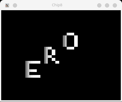
You can see the whole code changes in this commit.
Connecting our keyboard to CHIP8 Emulator Keyboard
As can be seen above, the only issue blocking us from being able to play a game in our Emulator is the redirecting input and output between our Emulator keyboard and our real computer keyboard. This can be easily done using SDL2 and mapping the keyboard keys, as can be seen below.
func (emu *Emulator) handleInput() {
	for event := sdl.PollEvent(); event != nil; event = sdl.PollEvent() {
		switch event.(type) {
		case *sdl.QuitEvent:
			println("Emulator Stopped")
			emu.running = false
			break
		case *sdl.KeyboardEvent:
			keyCode := event.(*sdl.KeyboardEvent).Keysym.Scancode
			switch keyCode {
			case 4:
				emu.input.registerKeyPress(0xC)
			case 5:
				emu.input.registerKeyPress(0xE)
			case 6:
				emu.input.registerKeyPress(0x3)
			case 7:
				emu.input.registerKeyPress(0x7)
			case 8:
				emu.input.registerKeyPress(0xB)
			...
With this we are now able to play the Astro Dodge game. Press 5 to start and 4 and 6 to move left and right respectively 😄
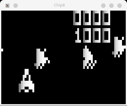
The final commit can be found here
Final Words
With this we come to an end of building a CHIP8 emulator. What can be done from here? Maybe clean up the code, add more tests? try out more games (We might find bugs in our interpreter 😄)
- I would highly encourage you to try out to build the CHIP8 interpeter yourselves. You already have everything you need, and it only takes 1 or 2 days. [return]
- CHIP8 memory already has built-in sprites representing the hexadecimal digits 0 through F. These sprites are 5 bytes long, or 8x5 pixels. They are stored in the Chip-8 memory (0x000 to 0x1FF). Please check this link for details. [return]